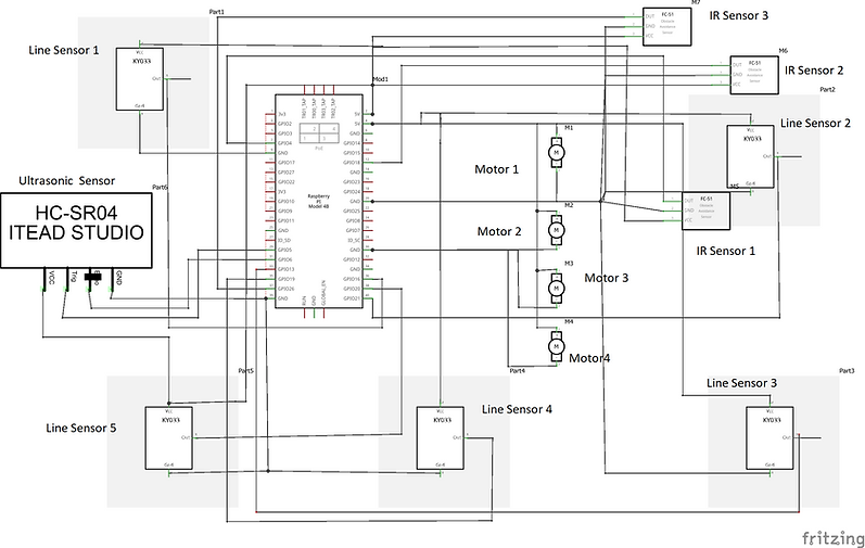
LINE FOLLOWING ROBOT WITH OBSTACLE DETECTION
ELECTRICAL SCHEMATICS
Created and Edited using Fritzing
IMPORTANT PARTS
Raspberry Pi
Motor Shield
DC Motor
Ultrasonic Sensor
Line sensor
IR sensor Module
RASPBERRY PI
Raspberry Pi is the name of a series of single-board computers made by the Raspberry Pi Foundation
The Raspberry Pi is a very cheap computer that runs Linux, but it also provides a set of GPIO (general purpose input/output) pins that allow you to control electronic components for physical computing and explore the Internet of Things (IoT).

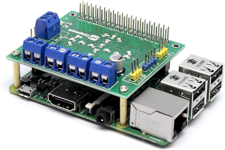
MOTOR SHIELD
Motor shield HAT is designed to control your Raspberry Pi based Robot. This board controls up to 4 DC motors.
It includes direction indicator LEDs to help configure motor output and connectors designed for plugging in IR and ultrasonic sensor modules to tell robots about its environment.
The board is designed specifically for the Raspberry Pi. Based around the L293D IC it is capable of driving 4 DC motors or 2 stepper motors.
The L293D is a dual full bridge driver that can output up to 1A per bridge with supply voltage up to 24V.
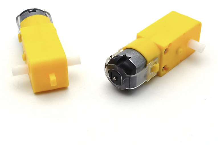
DC MOTOR
4 DC motors are used to drive the robot. DC motors are used to get good efficiency and control over the car.
DC Motor specification:
Motor Robot Gear Motor, Size(Approx): 7 x 2.2 x 1.9cm/2.76 x 0.87" x 0.75"
Maximum torque: 800gf cm min (3V) ; No-load speed: 1:48 (3V time)
Operating voltage: 3V~12VDC (recommended operating voltage of about 6 to 8V)
With EMC, strong magnetic, it has an anti-interference ability.
ULTRA SONIC SENSOR
Ultrasonic sensors measure distance by using ultrasonic waves.The sensor head emits an ultrasonic wave and receives the wave reflected back from the target. Ultrasonic Sensors measure the distance to the target by measuring the time between the emission and reception.
In this project, it is used to detect obstacle standing in front of robot car on the line.
Ultrasonic Specification:
Power Supply :+5V DC
Quiescent Current : <2mA
Working Current: 15mA
Effectual Angle: <15°
Ranging Distance : 2cm – 400 cm/1″ – 13ft
Resolution : 0.3 cm
Measuring Angle: 30 degree
Trigger Input Pulse width: 10uS
Dimension: 45mm x 20mm x 15mm

LINE SENSOR
Line sensor is light adaptable, high precision, with a pair of infrared transmitter and receiver. Transmitter tube emits a certain frequency of infrared ray, and when detecting the direction of an obstacle (reflector), the infrared receiver tube receiver is reflected back. When the indicator lights on,through the circuit, the signal output interface outputs the digital signal that can be detected by the potentiometer knob to adjust the distance, and the effective distance is from 2 ~ 40cm.
Line Sensor Specification:
Working voltage: DC 3.3V-5V
Working current: ≥ 20mA
Operating temperature: -10℃~+50℃
Detection distance: 2-40cm
IO Interface:3-wire interfaces
Output signal: TTL level (low level there is an obstacle, no obstacle high)
Adjustment: adjust multi-turn resistance
Effective angle: 35°

IR SENSOR MODULE
IR Sensor Module has an IR receiver and emitter combination. These sensors detect infrared light being emitted from the IR emitter.
In this project, it is used to detect side obstacles and to keep tracking obstacle while avoiding obstacle and come back on the line sensor.
IR sensor Module Specification:
5VDC Operating voltage
I/O pins are 5V and 3.3V compliant
Range: Up to 20cm
Adjustable Sensing range
Built-in Ambient Light Sensor
20mA supply current

BLOCK DIAGRAM

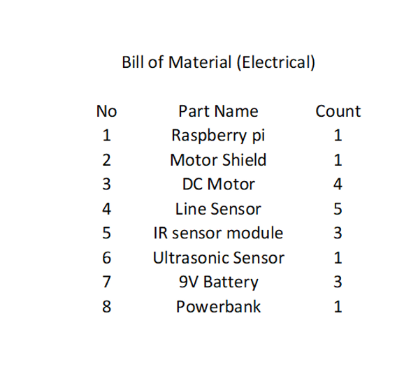
BOM
Built of Material